Lazmin LED Lattice Clock Kit Build
Lazmin LED Lattice Clock Kit Build.
09/04/2023
Hello Casio watch enthusiasts around the World. I hope you are all well.
In this post as the title suggests, I am going to be building an LED Lattice clock for my daughter as she loves lights and clocks. I know this has nothing to do with Casio watches, but it is a time piece and I thought some people may find it interesting as there is no information on the internet. It DOES NOT COME WITH ANY INSTRUCTIONS from the manufacturer. I did contact the seller but he replied, and I quote, "It's so simple, even a child could build it" and that was all the information I received. The advert did not say there would be no instructions supplied, I simply assumed there would be as will nearly everything. They also failed to advise that the LED's supplied in the kit are actually sub-miniature SMD (surface mount) components, which are absolutely miniscule in size. Working with normal size SMD components are difficult enough to hand solder, but these will test my skills if I can find out there orientation. All LED's are naturally a diode and diodes will only conduct electrons in one direction, therefore the direction of the LED is imperative. If the LED's are installed in the wrong direction, they will not work. Considering there are 288 LED's on the display, it is important they are inserted correctly first time. These components were designed to be installed by machine and soldered by a machine. The LED's simply would not survive being taken out and reinstalled.
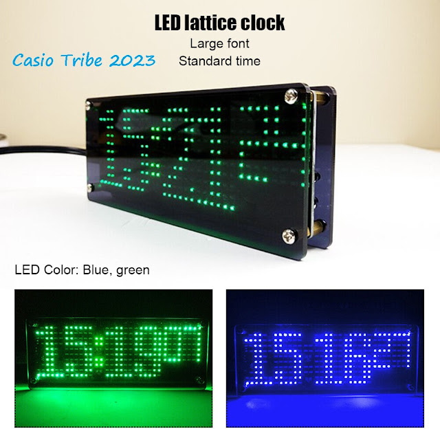
As you can see in the above picture, it is a lovely locking time piece. It can display either green or blue colours and I am also led to believe it has a temperature reading menu if you scroll through (If I ever get that far). The lattice display is made up of 288 sub-miniature LED's which makes it look super cool. The kit is made by a company called Lazmin and cost me £14 including delivery, which I thought was reasonable to say the least.
Above is a picture of the parts that come in the kit. I cannot tell you exactly what these parts are at the moment as there were no instructions, parts list or bill of materials supplied with the kit.
 Above is a picture of either side of the circuit board (PCB) supplied with the kit. The (top) front side is the display holding the LED's and the (bottom) rear holds the IC's (integrated circuits).
 And a picture of the whole kit. As you can see, the kit is supplied with a USB power cable and is powered via a 5 Volt DC power source (PC, PLUG).
Now, let me show you the size of one of the 288 LED's that need to be correctly fitted.
In the picture above, I used a ball point pen, a pair of tweezers and my spectacles as a scale reference. It is indicated by the yellow arrow. Too small? Let me zoom in a little.
As you can see, it is absolutely tiny. I would approximate it to be 2mm long and 0.6mm wide. To be openly honest, I was not expecting the LED's to be this small. I was in trouble as I was not equipped for this size component but I had a friend that does, so I loaned his.
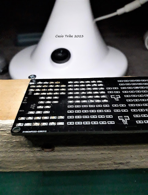
I also secured the PCB to a piece of wood to firstly secure the board from moving, and to raise the PCB into a better focal position for the magnifying glass. As you can see, I have already installed 2 LED's.
After 3 hours, I had installed and tested 80 LED's to the board. I tested them using continuity tester with the positive at the left (anode) and the negative to the right (cathode).
After another 3 hours, I had installed another 80 LED's, tested them for polarity and operation. I have now fitted 160 of the 288 LED's. However, during the careful fitting and soldering of the LED's, I have so far lost 5 and damaged 6.
There was no point in hanging around, so I spent another 4 hours fitting the last 128 LED's except one (yellow arrow). When I came to test this last LED it was not functioning, so I de-soldered it from the board. I will replace it as there are some spares in the kit. There is a lot of excess flux from the solder, so I will clean it carefully as it is a poisonous substance and should be removed.
As I previously stated, the seller said it was easy to assemble, I strongly disagree. Unless you are trained and have the correct tools, it would be almost impossible to get this kit working. I would NOT RECOMMEND this kit to the beginner or a novice alike. I would imagine even highly trained operators would find this a challenge, as I have.
After removing the excess flux from the front of the PCB, it was time to fit the IC's. I did this by first putting just a touch of solder on one of the corner solder pads, then heat up the pad and line up the IC correctly over each and every pad on the IC. Once the IC was correctly aligned, I soldered the opposite corner onto it's pad therefore securing the IC. I did this with all 7 IC's ensuring they were in the correct orientation (the right way around). Once all the IC's were in the correct position, I applied a small amount of this stuff.
It's called solder paste, combined with flux and cost me £5 including delivery. It is quite a runny mixture and quite poisonous. It has a shelf life of only 3 month and must be kept below 6 Degrees Centigrade. Only a small amount is needed for each component. This paste can be soldered either with a normal iron or a high temperature heat gun. I was advised the melting point of the paste is 183 Degrees Centigrade (which is quite low), and is ideal for this operation.
I would not advise to try to hand solder these IC's as it will be almost impossible and that is why I am using a dedicated high power heat gun designed especially for this kind of work.
After a short time, the heat gun melts the solder paste and it forms a wonderful soldered connection. As you can see the uniformity in each soldered connection. It gives a much better finish than trying to do it with a soldering iron and is perfect time after time. The lower melting point of the paste, ensures the LED's on the reverse side won't de-soldered when I am soldering the IC's on this side.
Again you can see the uniformity in the shape of the soldered connections. This procedure is also very reliable, with the low temperature ensures there will be no component damage.
After inspecting every IC pin on every IC, I then hand soldered in two SMD 10pico farad capacitors and a 10K Ohm SMD resistor. I also hand soldered in the 768KHz crystal. I then inserted the connection holder, capacitor and thermistor, turned the PCB over and soldered the USB connector on.
After every component was fitted, I installed the battery and plugged it in via the USB cable supplied, and to my joy, the little clock lit up. However, there were a couple of dead LED's that had to be replaced. It's a good job there are around 30 spare LED's in the kit!
Once the dead LED's had been replaced, I fitted the acrylic back plate (which has cut out's for the switches and the large capacitor) and the acrylic front plate.
Both the front and rear acrylic plates have a protective film that needs to be removed to reveal that beautiful shine. I think it looks awesome!
And when it's switched on!! It looks amazing in my humble opinion.
The display can be changed to blue however, as it came with no instructions, I do not know how to change it. It also can display day, date and temperature. I was able to work out how to set the time though with a little effort. To be honest, I'm just glad it's working and I can now pass it to my Daughter who absolutely loves it. Happy Days indeed!
As I said, the clock cost me £14 delivered and I was happy with that. I also spent around 14 hours building the clock, again I was happy with that. However, I also needed dedicated tools to complete the kit, that I was not made aware of and I'm not happy with that. The soldering station that I loaned from a friend was around £100, and without that, I could not complete the build. There are no instructions supplied in the kit and I'm not happy with that. After saying that, I should have expected it and should have been better prepared so I can only blame myself to be honest.
Remember the old saying,
"Fail to prepare, then prepare to fail".
So very true.
Well my fellow enthusiasts, that is it for this project and I hope you have enjoyed it, even though it is not Casio related. I hope you have learned something from this post to add to your own personal skill sets.
Until my next post, take care fellow Casio enthusiasts from around the World.
Casio Tribe 2023
09/04/2023


Comments
Post a Comment